简体中文
简体中文
 English
 عربى
عربى
NEWS
Home / News / Industry News / Progressive Die Design: Process, Strip Layout, Tolerances, and Tooling Costs
Content
An engineer sends a part print for a stainless steel bracket that will sit near a turbocharger in a new vehicle platform. The projected volume is 400,000 pieces per year, and one mounting hole must hold a tolerance of +/-0.05 mm. Within days, the tooling supplier responds with a strip layout showing how coil stock will be pierced, trimmed, formed, and cut off into the finished bracket at roughly 250 strokes per minute. That response is where progressive die design either earns its keep or starts to create problems.
Progressive die design is the arrangement of multiple stamping operations on a single die set so that each press stroke delivers a complete part. It deserves close attention because the layout of the die determines the quality of every part produced across the life of the tool, the cost of the tool itself, and the lead time between order and production.
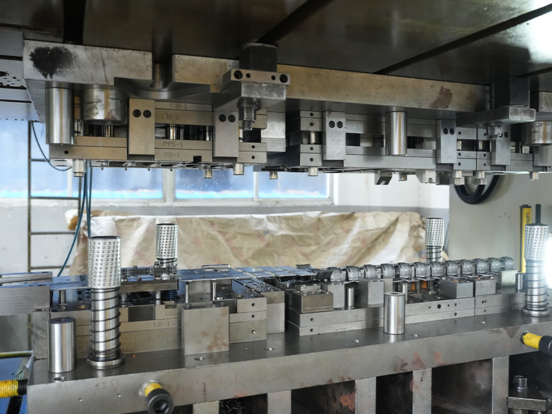
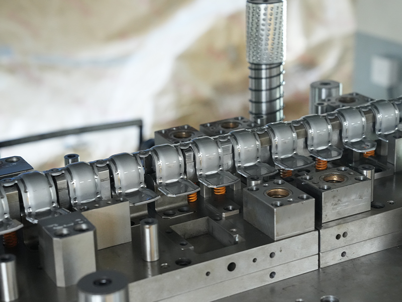
A progressive die works on a continuous strip of metal. The strip advances by a fixed distance, called the pitch or feed length, with every press stroke. At each station, one operation takes place: a pilot hole is pierced, a contour is trimmed, a flange is bent, a cup is drawn, or a feature is embossed. At the final station, the finished part is separated from the carrier strip that has carried it through the die.
The main elements of a progressive die design are:
The sequence and the carrier design are not details. They are the backbone of the whole process, because every downstream station depends on the material arriving at the right position in the right shape.
Progressive die design follows a repeatable workflow. Skipping any step usually shows up later as a problem on the press.
The strip layout is the most important step. A poor layout with an unstable carrier or weak piloting cannot be repaired by better machining; it fails on the press, sometimes only after thousands of parts have been made. For this reason, experienced die designers spend more time on the strip layout than on any other phase.
Material behavior is the starting point of every progressive die design. Harder grades such as 304, 316, and 410 stainless steel work harden during forming, so the die must leave enough clearance and sometimes include stress-relief steps. Aluminum and its alloys form easily but tend to gall on tool surfaces, so lubrication, polished tool steel, and controlled clearances are essential. Copper alloys offer excellent conductivity and ductility but require sharp tooling to keep burrs off electrical contact areas. Zinc-coated or galvanized steel can lose its coating at sheared edges, so the designer must control clearance and edge geometry to protect the layer.
| Material | Typical progressive die parts | Design considerations |
|---|---|---|
| Stainless steel (304, 316, 410) | Brackets, gaskets, heat shields | Work hardens; needs generous clearances and sometimes post-stamping treatment |
| Aluminum and aluminum alloys | Heat sinks, charging pile plugs | Light and formable; watch galling, springback, and surface finish |
| Copper and brass | Connectors, pins, bearing caps | Excellent formability; sharp tooling required for burr control |
| Zinc and galvanized steel | Motor housings, shock absorbers | Coating can flake; tight clearance preserves edge protection |
An automotive steel flange is a good example of a part that looks simple but depends heavily on the progression. The flange geometry, hole pattern, and flatness requirements usually force the designer to combine piercing, trimming, and forming stations, and the die must hold dimensional stability over long production runs.
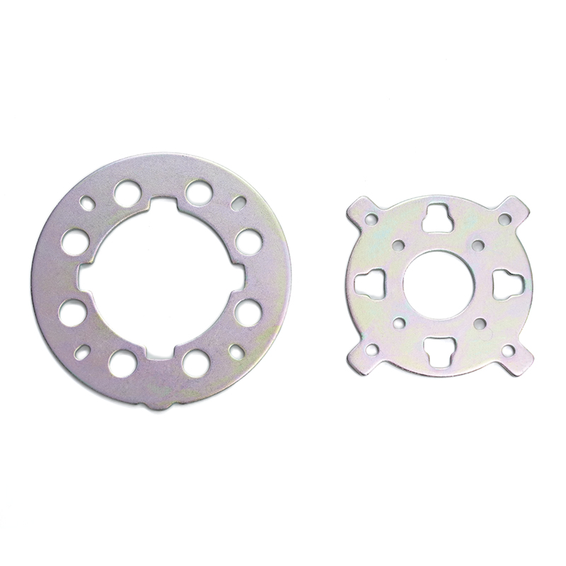 Custom Automotive Steel Flange Suppliers, CompanyChangzhou Dingjia Metal Technology Co., Ltd. is China Custom Automotive Steel Flange Suppliers and Automotive Steel Flange Company, Our a...View Product →
The pitch between stations defines the feed length and, in turn, the number of parts produced per stroke. A shorter pitch increases output but may leave too little room for deep forming tools. The carrier strip must stay strong enough to move the part through every station, yet narrow enough to keep material utilization high. Piloting is only secure when the pilot holes survive until the final station, so the layout must not cut them away too early. These trade-offs are why strip layout reviews matter before tooling begins.
Modern progressive die design routinely holds hole positions to +/-0.05 mm and flatness within 0.1 mm for small-to-medium parts, but the achievable values depend on material thickness, strip width, part size, and the number of stations. In high-temperature engine applications, a stainless steel turbo sealing gasket demands tight flatness and burr-free edges because any imperfection can compromise the seal. A die designer who understands the function of each feature knows which tolerances are critical and which are secondary, and that knowledge directly affects tooling cost.
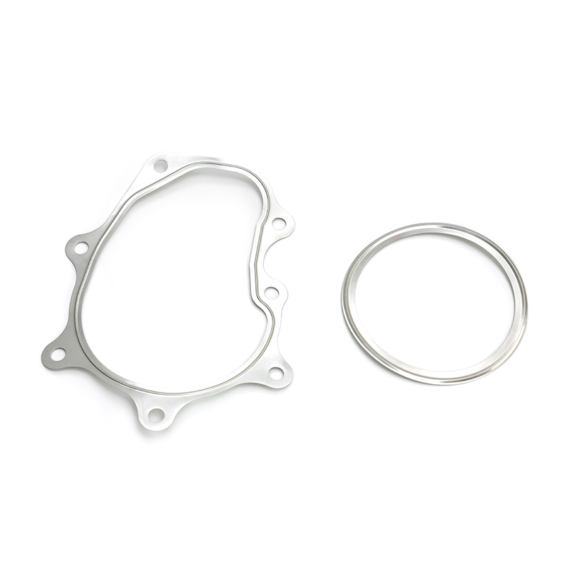 Custom Stainless Steel Turbo Sealing Gasket Suppliers, CompanyChangzhou Dingjia Metal Technology Co., Ltd. is China Custom Stainless Steel Turbo Sealing Gasket Suppliers and Stainless Steel Turbo Sea...View Product →
A progressive die is rarely the cheapest way to build a prototype, and it is not the right answer for every part. The tool itself can cost a few thousand dollars for a simple two-station design or well over six figures for a complex die with many forming operations. The economics usually favor a progressive die when the annual volume is high enough that the low per-part cost offsets the tooling investment.
On schedule, a typical progressive die for a small stamping takes four to ten weeks to design and build. Complex geometry, hard materials, and tight tolerances extend that window because tryout and sampling take longer. Plan for at least one round of sample approvals, and confirm who carries the cost of changes caused by design updates on the customer side.
Major cost drivers in a progressive die design include:
Even experienced teams see the same issues repeat in progressive die design. Recognizing these problems early reduces risk for the buyer.
Most of these issues share one root cause: the die is designed before the material and process are fully understood. A supplier with production experience across a range of materials can flag these problems during quotation instead of during tryout.
The right partner brings more than a press and a die. Look for a supplier that designs and builds its own progressive dies, has the press capacity to run production in-house, and can demonstrate experience with both ferrous and nonferrous metals. A quality management system adds confidence that the tooling, sampling, and production steps are documented. Most importantly, the supplier should be willing to discuss strip layout, tolerance strategy, and material choice before the quotation is locked in.
At Changzhou Dingjia Metal Technology, the same engineering team that designs the progressive die also supports die assembly and the stamping line. Our stamping capacity reaches 500 tons, and our production range covers stainless steel, iron, automotive steel, aluminum, copper, and zinc-based parts. That structure means material knowledge and manufacturing feedback go directly into every design review. For new energy charging pile projects, we have also applied progressive die approaches to components such as the stamped aluminum fan heat plate, where thermal performance, flatness, and surface quality all matter.
 Custom Stamped Aluminum Fan Heat Plate New Energy Charging Pile Plug Suppliers, Changzhou Dingjia Metal Technology Co., Ltd. is China Custom Stamped Aluminum Fan Heat Plate New Energy Charging Pile Plug Suppliers and ...View Product →
To prepare for your next part, review our practical guide to precision stamping parts to see how material, tooling, and production factors interact. If you already have a print or a 3D model, you can contact the team to discuss the strip layout and tooling plan before you commit to a full investment.
Progressive die design rewards engineers and buyers who look beyond the quotation. The strip layout, the station sequence, the tool steel selection, and the material knowledge behind the die all decide whether your part arrives on time, holds its tolerance, and stays affordable at volume. Ask to see the layout, question the assumptions, and choose a partner whose die engineers will talk to you before the steel is cut.
A Practical Guide to Iron Stamping Parts: Materials, Process, and Supplier Selection
2026-08-14Progressive Die Design: How Engineers Turn a Part Print into High-Volume Production
2026-08-27Your email address will not be published. Required fields are marked *
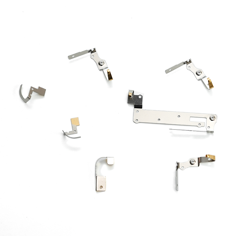
The stamped stainless steel electronic plug-in is a precision-engineered component manufactured using advanced stamping techniques. Made from high-quality stainless steel, this part offers exceptional...
See Details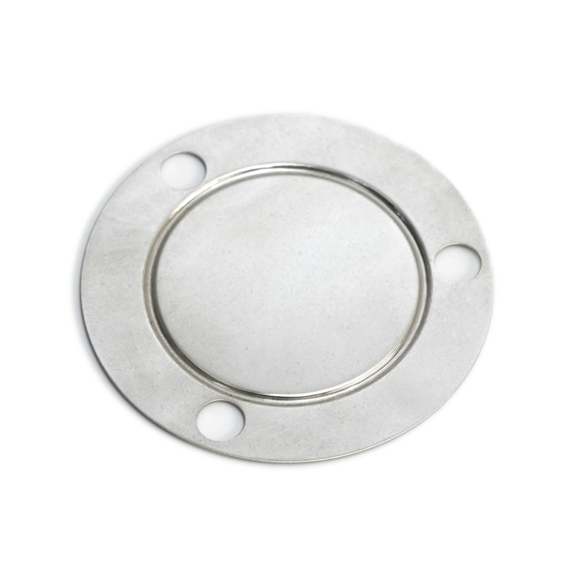
Our wear-resistant and high-pressure stainless steel shim is engineered to withstand conditions and provide exceptional performance in a variety of industrial applications. Made from premium-grade sta...
See Details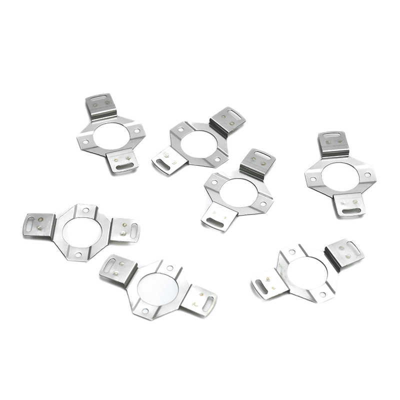
Our wear-resistant stainless steel bracket is engineered for high-performance applications where durability and strength are paramount. Made from premium stainless steel, this bracket is designed to w...
See Details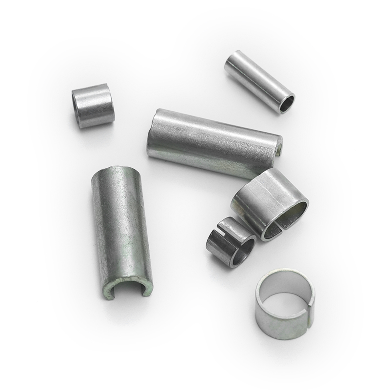
Our black malleable iron bushings are durable, high-quality components designed for various industrial applications, offering exceptional strength, resistance to wear, and long-term performance. These...
See Details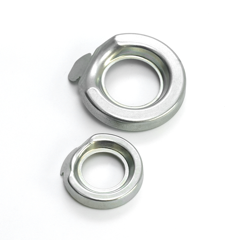
The Stamped Iron Oil Baffle is a critical component in engine and transmission systems, designed to manage and control the flow of oil within mechanical assemblies. Produced using precision metal stam...
See Details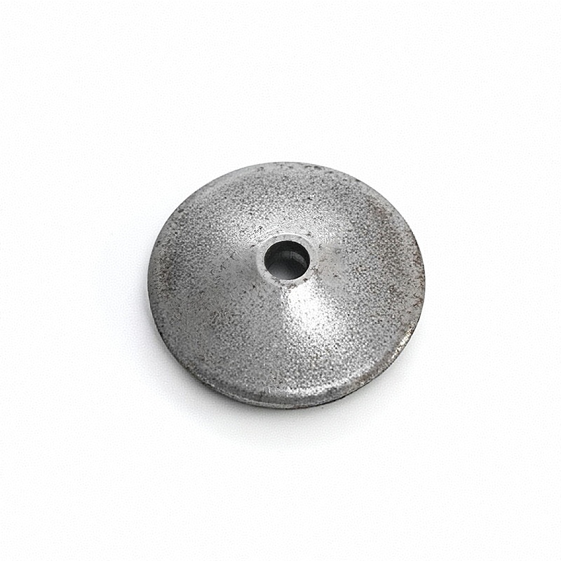
Our iron gasket is a high-performance sealing solution designed to provide durable and reliable performance in a wide range of industrial applications. Manufactured from high-quality iron materials, t...
See Details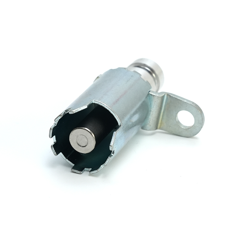
The Stamped Iron Valve Core Assembly is manufactured using stamping technology and made from high-quality iron material, precisely stamped into shape. This component is widely used in various fluid co...
See Details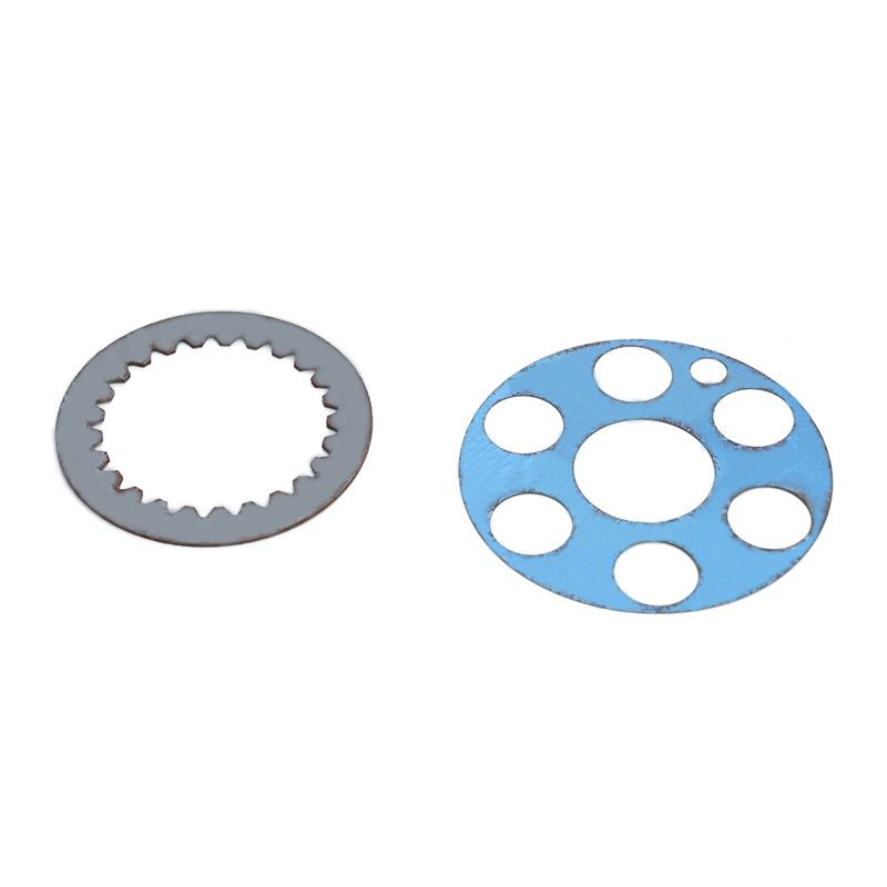
Our iron friction plate is a high-quality, durable component designed for use in a variety of mechanical systems requiring efficient energy transfer and heat resistance. Manufactured using premium-gra...
See Details
The Stamped Aluminum Fan Heat Plate for New Energy Charging Pile Plug is a key component manufactured from aluminum alloy using stamping technology, widely used in the plug section of new energy vehic...
See Details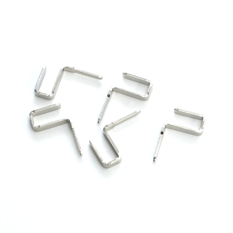
Tinned copper pins are precision-engineered electrical connectors designed to provide reliable and efficient performance in a wide range of applications. Made from high-quality copper wire, these pins...
See Details
The Stamped Copper Silver-Plated New Energy Charging Pile Plug is a high-performance connector specially designed for new energy electric vehicle charging stations. Made from high-quality copper mater...
See Details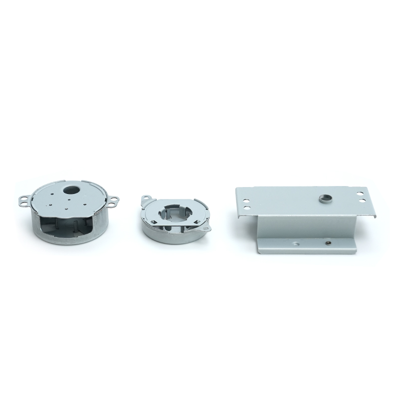
Our galvanized sheet motor housing offers robust protection and longevity for a wide range of electric motors used in various industries. Crafted from high-quality galvanized steel, this motor housing...
See Detailscontact details
Address: No.6 Qiasheng North Road,Caoqiao Industrial Park,Xueyan Town,Wujin District,Changzhou City,Jiangsu Province
TEL: 86-15050692548
If You Are Interested In Our Products, Please Consult Us
 Ferrous & Non-Ferrous Metal Stampings Manufacturers