简体中文
简体中文
 English
 عربى
عربى
NEWS
Home / News / Industry News / Progressive Die Design: How Engineers Turn a Part Print into High-Volume Production
Content
Ask two stamping shops to quote the same flat terminal and you will often get two very different answers: one built around a simple single-stage die with low tooling cost and a piece price that never really falls, the other around a progressive die that costs more upfront and produces parts for a fraction of that once it runs. The difference between those quotes is progressive die design—the engineering work that decides how a metal strip moves through a tool, what happens at each station, and how much of your budget ends up as scrap, rework, and downtime. For high-volume stamped parts, this design phase sets the piece price, the lead time, and the consistency you will live with for the life of the program. Here is how the work is actually done, and where it pays to push back on the details.
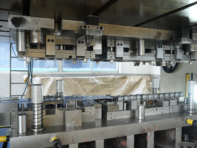
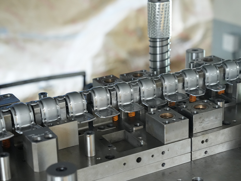
A progressive die is a single tool containing a sequence of stations, and a coil of metal strip feeds through it one pitch per press stroke. Each stroke advances the strip, and every station performs one operation—piercing, blanking, coining, bending, forming, and finally cutting the finished part free. Early stations usually pierce pilot holes and internal features while the strip is still flat, middle stations shape the part, and the last station separates it from the carrier strip that has carried it through the whole die.
The design phase is where that tool is born. Before any tool steel is cut, a die designer studies the part print, fixes the order of operations, lays out the strip, and specifies clearances, punches, forming inserts, and sensors. That layout determines the press size required, the scrap rate, the tolerances the tool can hold, and how easy it will be to maintain for years of running. A weak design surfaces later as burrs, distorted bends, and unplanned stoppages—problems far cheaper to resolve on paper than in hardened steel. For the finer detail on strip layouts, tolerance stacking, and tooling budgets, see our separate guide to progressive die design process, strip layout, tolerances, and tooling costs.
Design starts with the drawing, not with the die. The designer checks whether the part is stampable as drawn: hole diameters relative to material thickness, distances from holes to edges and bend lines, bend radii, and any feature that would force thinning or tearing. Two rules of thumb do much of the work here—a hole generally needs about two material thicknesses of clearance from an edge or a bend to avoid distorting as the metal flows, and inside bend radii tighter than roughly one material thickness risk cracking in harder alloys. Caught at the drawing stage, these issues cost a conversation; caught after the tool is built, they cost a rebuild.
Next comes the strip layout: where the part sits in the strip, how wide the strip runs, how much web remains between parts, and what each station contributes. A typical sequence follows this order:
Every added station enlarges the die, raises its price, and adds another point to maintain, so designers constantly weigh whether features can share a station or whether a sharp form should be split into two gentler steps.
Critical features are normally placed directly after a pilot station, because feed error accumulates with every pitch. With pilot registration, piercing in the region of ±0.05 mm is a realistic expectation from well-built tooling, while unguided feeding alone will not hold that consistently. The carrier—the ribbon of material connecting parts through the die—is designed at the same time: solid carriers give the strip stability, while lanced carriers let sections of the part be lifted or bent while still attached, which is what makes complex single-pass forms possible.
Conclusion first: the most expensive decisions are the ones that look small on the drawing. A tight tolerance on a non-critical feature, an unspecified burr direction, or a material chosen for convenience can add cost at every stroke for the life of the tool. The main decisions worth settling early are summarized below.
| Design decision | Why it matters | What it means for the buyer |
|---|---|---|
| Number of stations | Each station adds die size, components, and maintenance points | Fewer stations usually lower tooling cost; more stations can reduce thinning and scrap on complex forms |
| Material selection | Springback, die wear, and lubrication needs differ by alloy | Higher-wear alloys may raise tooling cost but reduce part failures in service |
| Tolerance callouts | Only critical-to-function features need tight control | Tightening every tolerance inflates cost without improving the product |
| Burr direction | Burrs face the punch side; mating or sealing surfaces may need the burr-free face specified | Prevents assembly problems and unplanned deburring operations |
| Carrier and web design | Determines how much strip material becomes scrap | Better material utilization lowers the piece price on long-running parts |
Material choice deserves particular attention because it ripples through everything downstream. Stainless steel resists corrosion but work-hardens and wears punches faster than carbon steel; copper alloys conduct well but are softer and demand sharper, more carefully maintained tooling; aluminum is light but moves less predictably during forming. Surface requirements belong in the same conversation: where a part carries current or faces corrosive service, the alloy and the plating should be fixed before tooling design starts, since they decide contact resistance and corrosion behavior for the life of the component. One example from our own line:
tinned copper pins for solenoid valve assemblies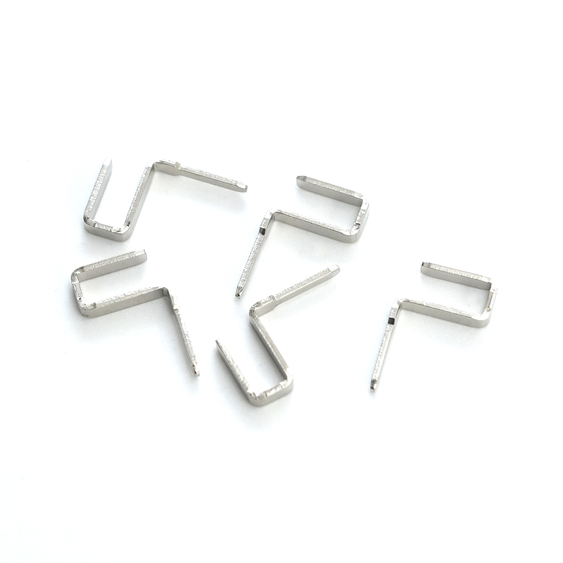 Tinned Copper Pins for Electrical ConnectionsTinned copper pins combine copper's conductivity with a tin coating that resists oxidation and corrosion. They illustrate how alloy and plating choices, made before tooling design, determine contact resistance over the component's life.View Product →
Progressive dies earn their keep in volume. Once a tool runs, small parts can be produced at hundreds of strokes per minute with almost no handling, and every part leaves the die with the same geometry because the tool—not the operator—controls where features sit. Coil feeds, scrap cutters, and in-die sensors make the process automation-friendly, which is why the per-part cost drops so sharply once the tooling investment has been absorbed.
The economics fail just as clearly in the other direction. Tooling only pays back across sustained volumes, so a prototype batch or a few thousand simple washers a year may be cheaper with single-stage tooling or cutting. Changes after the die is built are expensive, because adding a feature can force a new strip layout and new stations. Very large or thick parts can exceed practical strip widths and press capacity. A straightforward test: if the part will run for years at steady volume and its geometry is stampable as drawn, progressive design usually wins; if volumes are low or the design is still moving, it rarely does.
Most buyers meet progressive die design through the parts it produces rather than the tool itself, and three industries account for most of that demand.
Connector terminals, contact pins, lead frames, EMI shielding cans, and grounding contacts are classic progressive die products: thin, flat, high-volume, and made from conductive alloys such as phosphor bronze, brass, and plated copper. These are among the tightest-tolerance parts in any progressive die, because contact force and insertion fit depend on geometry holding steady stroke after stroke. One example from our catalog:
phosphor bronze connectors for stable electrical contact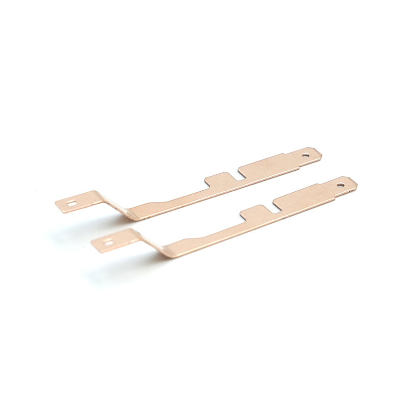 Phosphor Bronze Connector TerminalsMade from copper-tin-phosphorus alloy, these connectors offer conductivity, corrosion resistance, and fatigue strength. They typify the thin, high-volume conductive parts where tight tolerances depend on stable progressive die geometry.View Product →
Brackets, sealing gaskets, shims, heat shields, and seat hardware run progressively because vehicle programs consume them in large, steady quantities. Corrosion and temperature resistance often drive the material call—stainless steel near hot exhaust components, high-strength steel for structural brackets—and that choice in turn shapes die clearances and tool steel selection. A representative part from our automotive range:
stainless steel turbo sealing gaskets for high-temperature sealing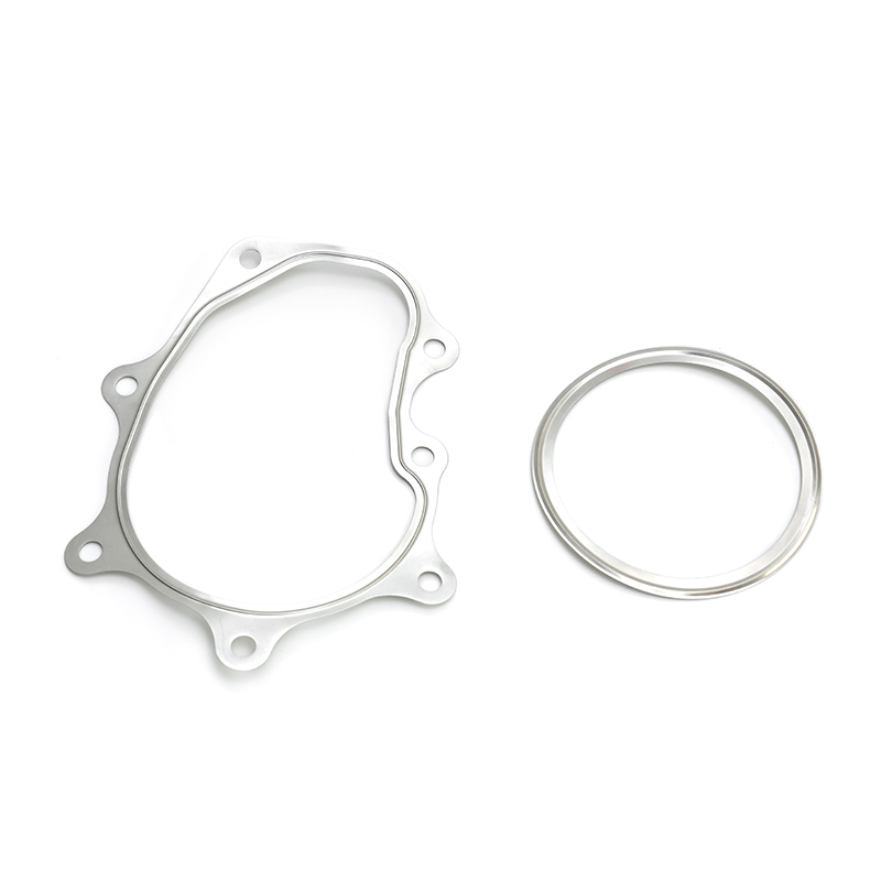 Stainless Steel Turbo Sealing GasketA multi-layer stainless steel gasket built to seal turbocharger connections against heat, pressure, and vibration. It shows how corrosion and temperature requirements drive material selection and tooling decisions in automotive progressive stamping.View Product →
Medical device and precision instrument manufacturers turn to progressive tools when volumes justify the investment, trading a longer validation phase upfront for repeatable dimensions across every lot that follows.
A short checklist saves months of rework later, and we recommend settling each item before signing off on a progressive tool:
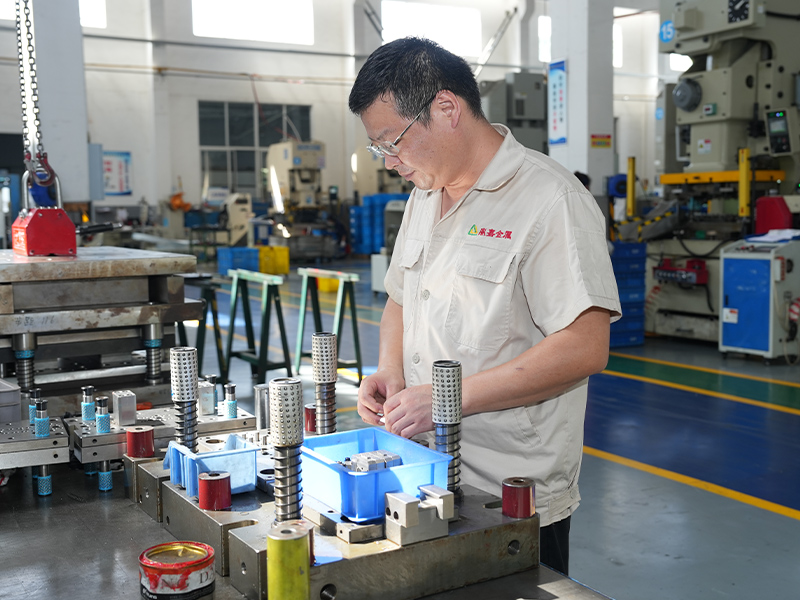
One factor matters as much as the design itself: whether the same team designs, builds, and runs the tool. At Changzhou Dingjia Metal Technology, die design, assembly, and maintenance sit in-house alongside 24 presses with up to 500 tons of stamping capacity serving automotive, electronics, and medical customers, so feedback from the press floor reaches our designers directly and corrections take days rather than weeks. If you are weighing a progressive die for an upcoming part, send us your drawing and target volumes, and we will review the strip layout with you before any steel is cut.
Progressive Die Design: Process, Strip Layout, Tolerances, and Tooling Costs
2026-08-21Medical Device Stamping: Materials, Tolerances, and How to Source Reliable Parts
2026-09-04Your email address will not be published. Required fields are marked *

Our stainless steel stamping metal shrapnel is a high-performance component designed to meet the demanding requirements of industries that need precision, durability, and resistance to harsh environme...
See Details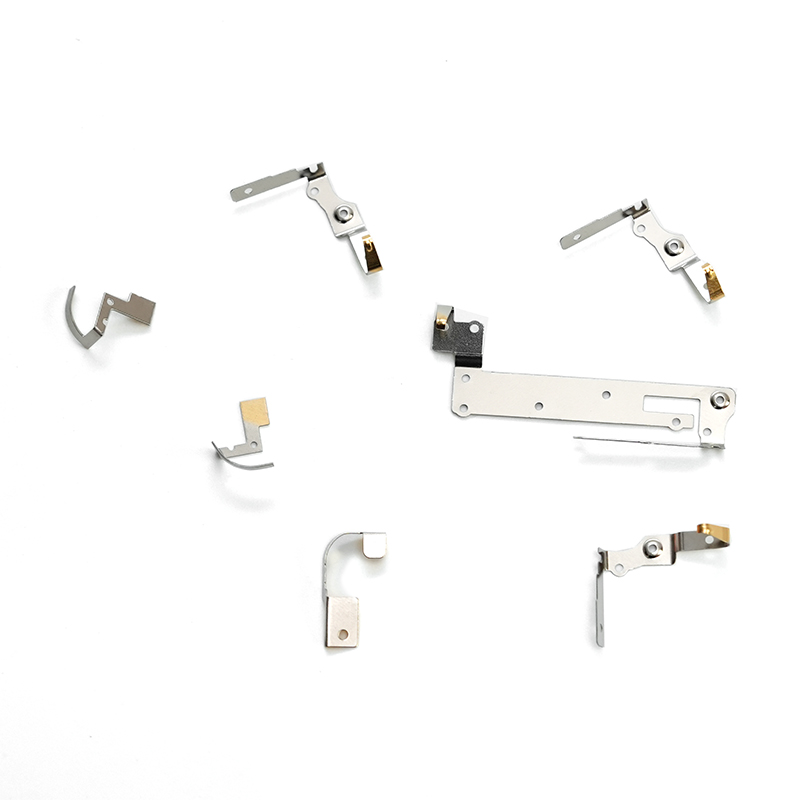
The stamped stainless steel electronic plug-in is a precision-engineered component manufactured using advanced stamping techniques. Made from high-quality stainless steel, this part offers exceptional...
See Details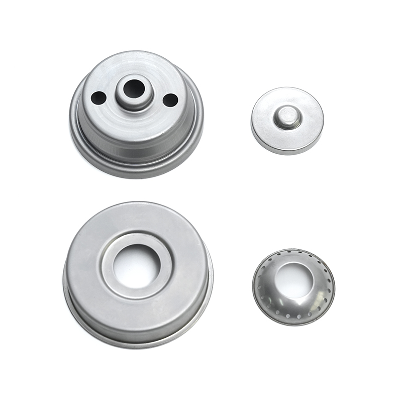
The Stamped Stainless Steel Heat Shield is a precision-formed automotive component designed to protect critical systems from excessive heat. Manufactured using advanced stamping technology, this heat ...
See Details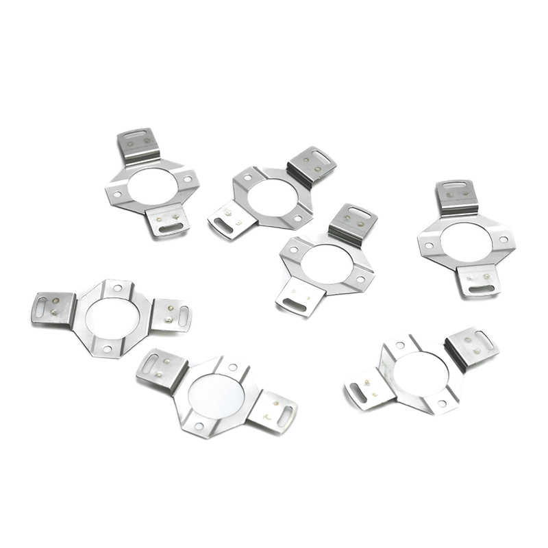
Our wear-resistant stainless steel bracket is engineered for high-performance applications where durability and strength are paramount. Made from premium stainless steel, this bracket is designed to w...
See Details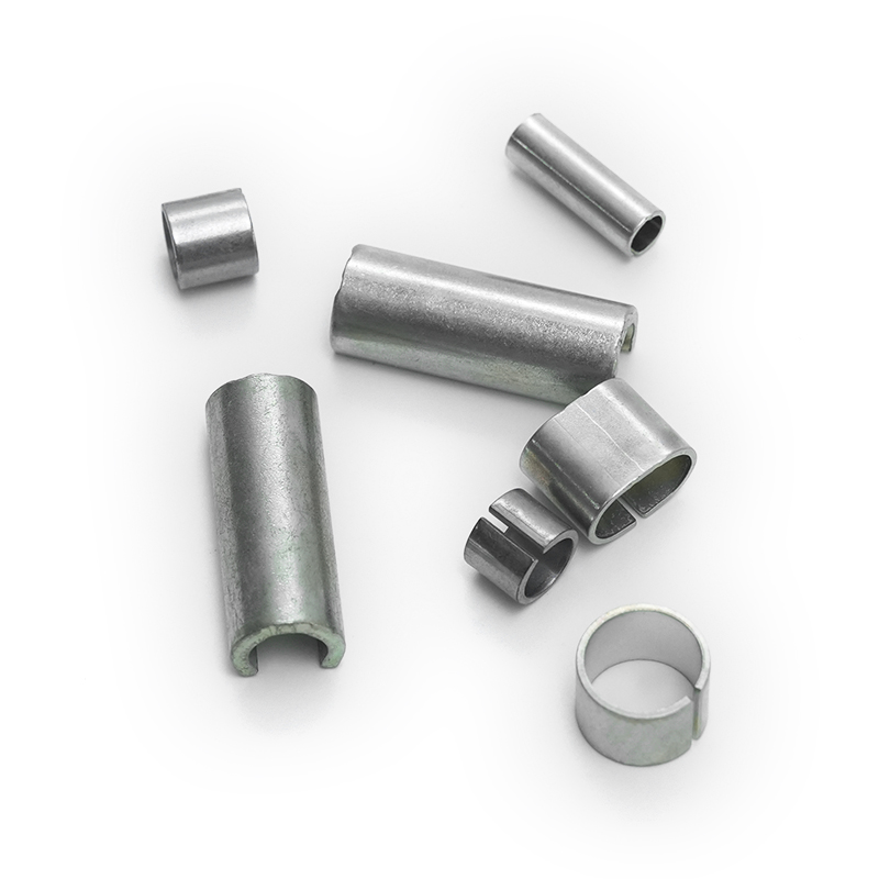
Our black malleable iron bushings are durable, high-quality components designed for various industrial applications, offering exceptional strength, resistance to wear, and long-term performance. These...
See Details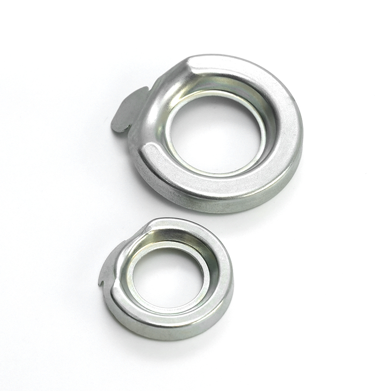
The Stamped Iron Oil Baffle is a critical component in engine and transmission systems, designed to manage and control the flow of oil within mechanical assemblies. Produced using precision metal stam...
See Details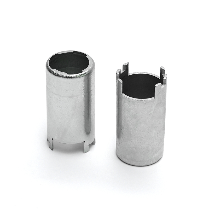
The Stamped Iron Solenoid Valve Housing is a precision-engineered component designed to encase and protect solenoid valve systems. Manufactured using advanced metal stamping processes such as deep dra...
See Details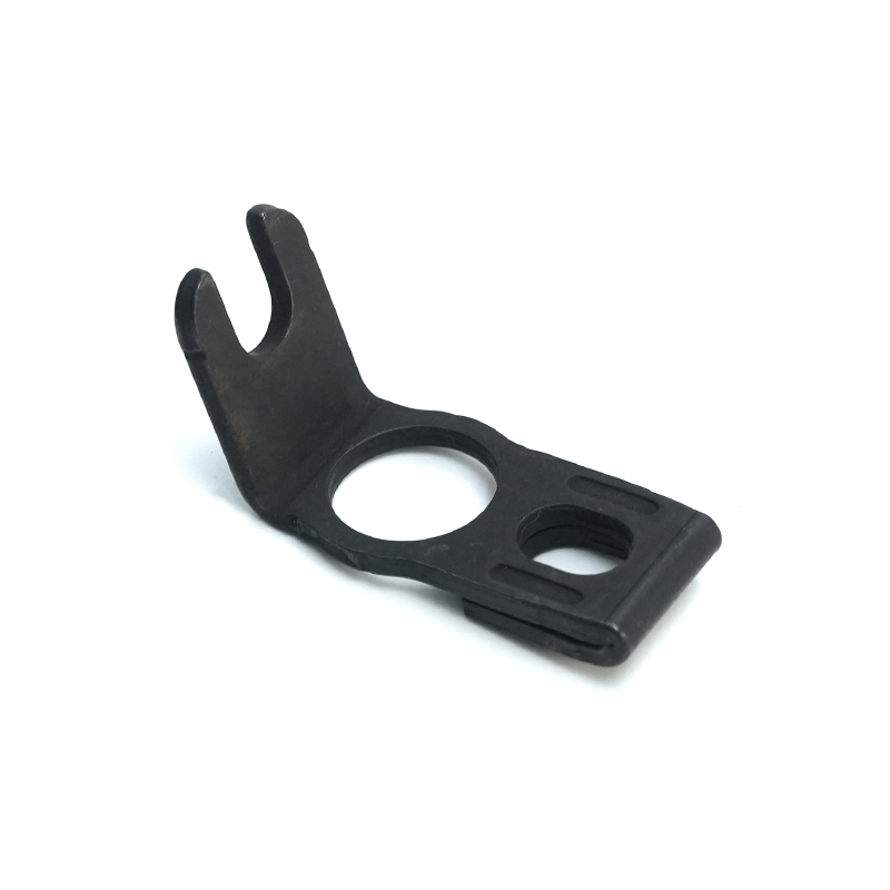
The iron gear engagement bracket is a robust, precision-engineered component designed to ensure the secure and efficient engagement of gears in various mechanical systems. Constructed from high-qualit...
See Details
Our automotive steel flange is engineered for precision, durability, and exceptional performance in various automotive applications. Made from high-quality carbon steel, stainless steel, or alloy stee...
See Details
Brass bearing dust caps are essential components designed to protect bearings and other mechanical parts from dirt, dust, moisture, and contaminants that can cause premature wear and damage. These dus...
See Details
Tinned copper pins are precision-engineered electrical connectors designed to provide reliable and efficient performance in a wide range of applications. Made from high-quality copper wire, these pins...
See Details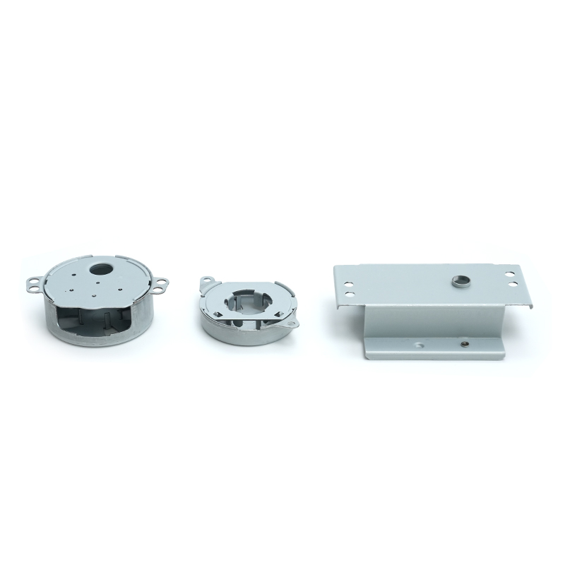
Our galvanized sheet motor housing offers robust protection and longevity for a wide range of electric motors used in various industries. Crafted from high-quality galvanized steel, this motor housing...
See Detailscontact details
Address: No.6 Qiasheng North Road,Caoqiao Industrial Park,Xueyan Town,Wujin District,Changzhou City,Jiangsu Province
TEL: 86-15050692548
If You Are Interested In Our Products, Please Consult Us
 Ferrous & Non-Ferrous Metal Stampings Manufacturers