 简体中文
简体中文
 English
 عربى
عربى
Content
- 1 What Is a Stamped Iron Oil Baffle
- 2 Manufacturing Process and Material Selection
- 3 Design Features and Engineering Considerations
- 4 Performance Benefits in Lubrication Systems
- 5 Application Sectors and Use Cases
- 6 Installation and Maintenance Considerations
- 7 Cost Analysis and Economic Considerations
- 8 Quality Control and Testing Standards
- 9 Future Developments and Innovation Trends
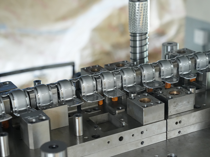
What Is a Stamped Iron Oil Baffle
A stamped iron oil baffle is a precision-formed sheet metal component designed to control oil flow and prevent oil starvation in engines and mechanical systems. Manufactured through high-pressure stamping processes, these baffles use iron or steel sheets typically ranging from 0.8mm to 2.0mm in thickness to create complex geometries that manage lubricant distribution under dynamic operating conditions.
The primary function involves redirecting oil away from moving components during acceleration, cornering, or incline operations while maintaining adequate lubrication to critical engine parts. Modern stamped iron oil baffles incorporate ventilation holes, reinforcement ribs, and mounting flanges—all formed in a single stamping operation to ensure structural integrity and cost-effectiveness.
Manufacturing Process and Material Selection
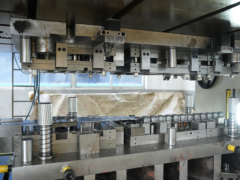
Stamping Technology
The stamping process for oil baffles utilizes progressive dies or transfer dies capable of generating forces between 80 to 300 tons depending on part complexity. Cold-rolled steel (CRS) or galvanized iron sheets undergo blanking, piercing, forming, and trimming operations in rapid succession, achieving production rates of 15 to 40 parts per minute in high-volume automotive applications.
Advanced stamping facilities employ servo-driven presses that provide precise control over ram speed and position, enabling the formation of deep-drawn features and tight-radius bends without material cracking. Tool steel dies with hardness ratings of 58-62 HRC ensure dimensional consistency across production runs exceeding 500,000 cycles.
Material Specifications
Material selection balances formability, corrosion resistance, and thermal stability:
- SPCC (Cold-rolled carbon steel): Most common choice offering excellent formability and cost efficiency for standard applications
- SECC (Electro-galvanized steel): Provides zinc coating protection against corrosion in humid environments
- SPHC (Hot-rolled pickled steel): Used for heavier-gauge baffles requiring superior strength
- Stainless steel 304/316: Reserved for high-performance or marine applications where corrosion resistance is critical
| Material Type | Thickness Range (mm) | Tensile Strength (MPa) | Corrosion Rating | Relative Cost |
|---|---|---|---|---|
| SPCC | 0.8-1.5 | 270-350 | Low | 1.0x |
| SECC | 0.8-1.5 | 270-350 | Medium | 1.3x |
| SPHC | 1.2-2.0 | 290-380 | Low | 0.9x |
| SS 304 | 0.8-1.5 | 520-720 | High | 4.2x |
Design Features and Engineering Considerations
Geometrical Configuration
Effective oil baffle design incorporates multiple functional zones optimized through computational fluid dynamics (CFD) analysis. The primary containment area features vertical walls with heights ranging from 25mm to 80mm that create oil reservoirs preventing pump starvation during lateral acceleration forces up to 1.2g in performance vehicles.
Ventilation apertures are strategically positioned to allow air release while minimizing oil escape during pressure fluctuations. Typical hole diameters range from 6mm to 12mm, with total open area calculated to maintain crankcase breathing capacity between 0.15 to 0.35 liters per second at normal operating speeds.
Structural Reinforcement
Stamped baffles incorporate embossed ribs or beads that increase rigidity without adding material thickness. These reinforcement features, typically 3-5mm in depth, enhance the section modulus by 200-400% compared to flat panels, enabling thinner gauge materials that reduce overall weight while maintaining structural integrity under vibration and thermal cycling.
Mounting flanges with pre-pierced bolt holes facilitate secure installation to oil pan floors or crankcase structures. Hole spacing follows standardized patterns with M6 or M8 fastener compatibility, ensuring reliable sealing through gasket compression or RTV silicone application.
Performance Benefits in Lubrication Systems
Implementation of stamped iron oil baffles delivers measurable improvements in engine reliability and operational efficiency across diverse applications:
Oil Starvation Prevention
Testing data from automotive OEMs demonstrates that properly designed baffles reduce oil pickup exposure incidents by 85-95% during cornering maneuvers. By maintaining consistent oil presence at the pump inlet, bearing lubrication remains uninterrupted even under sustained 0.9g lateral acceleration, preventing catastrophic bearing failure that would otherwise occur within 3-5 seconds of oil supply loss.
Windage Reduction
Oil baffles minimize crankshaft contact with bulk oil in the sump, reducing parasitic losses from oil churning. Dynamometer studies show that effective baffling systems recover 2-4 horsepower in high-RPM engines by decreasing windage drag coefficients from approximately 0.42 to 0.28. This translates to measurable fuel economy improvements of 0.3-0.6% in steady-state highway driving conditions.
Aeration Control
Compartmentalized baffle designs separate the churning zone from the oil pickup area, allowing entrained air bubbles to escape before oil recirculation. Laboratory analysis indicates that baffle-equipped systems maintain oil aeration levels below 3% by volume compared to 8-12% in unbaffled configurations, preserving lubricant film strength and heat transfer properties.
Application Sectors and Use Cases
Automotive Industry
Passenger vehicles utilize stamped iron baffles in both longitudinal and transverse engine configurations. High-performance variants feature multiple compartments with trapdoor valves that permit oil flow during normal operation but seal during aggressive driving. Production volumes for automotive baffles exceed 75 million units annually globally, with pricing ranging from $2.50 to $8.00 per unit depending on complexity.
Motorcycle and Powersports
Motorcycle applications demand compact baffle designs that accommodate limited sump volumes while managing extreme lean angles up to 55 degrees. Stamped baffles in this sector often integrate with oil screen assemblies, combining filtration and oil control in single components weighing less than 150 grams.
Industrial Equipment
Stationary and mobile industrial engines employ heavier-gauge stamped baffles to withstand continuous-duty cycles and contaminated operating environments. Construction equipment, agricultural machinery, and generator sets benefit from baffle systems that maintain lubrication during variable inclination angles and vibration frequencies between 10-150 Hz.
Marine Applications
Marine engines face unique challenges from prolonged pitch and roll motion combined with saltwater exposure. Galvanized or stainless steel stamped baffles with enhanced corrosion protection maintain oil control in conditions where vessel attitudes vary ±15 degrees continuously, preventing pump cavitation that would compromise engine cooling and bearing protection.
Installation and Maintenance Considerations
Proper Installation Procedures
Successful baffle installation requires attention to sealing interface preparation and fastener torque specifications. Mounting surfaces should be cleaned with solvent to remove manufacturing oils and residual gasket material. Torque values for M6 fasteners typically range from 8-12 Nm, while M8 fasteners require 18-25 Nm applied in cross-pattern sequence to ensure uniform gasket loading.
Clearance verification between baffle structures and rotating components is critical—minimum gaps of 5mm should be maintained between the baffle and crankshaft counterweights to prevent contact during thermal expansion. Some high-performance applications utilize adjustable baffle mounts allowing fine-tuning of position relative to oil pickup depth.
Service Life and Inspection
Stamped iron baffles demonstrate exceptional durability with service lives matching engine overhaul intervals of 200,000-300,000 miles in automotive applications. Inspection during routine oil pan removal should check for:
- Corrosion penetration or surface scaling exceeding 0.5mm depth
- Structural deformation from impact or overtightening
- Mounting hole elongation or fastener thread damage
- Sludge accumulation blocking ventilation apertures
Baffles showing signs of degradation should be replaced rather than repaired, as compromised structural integrity can lead to catastrophic failure during high-stress operating conditions.
Cost Analysis and Economic Considerations
The economic advantage of stamped iron oil baffles stems from high-volume manufacturing efficiency and material optimization. Tooling investment for progressive dies ranges from $15,000 to $65,000 depending on part complexity, with amortization occurring over production runs of 50,000-100,000 units.
Material costs constitute 40-50% of total production expense, with typical consumption of 0.08-0.15 kg of steel per baffle. At current cold-rolled steel pricing of $0.75-$0.95 per kilogram, raw material costs remain competitive compared to alternative manufacturing methods such as casting or fabrication.
| Manufacturing Method | Tooling Cost | Unit Cost (10K qty) | Lead Time | Design Flexibility |
|---|---|---|---|---|
| Stamping | $25,000-$65,000 | $3.20-$7.50 | 8-12 weeks | Medium |
| Die Casting | $35,000-$85,000 | $5.80-$11.20 | 10-14 weeks | High |
| Welded Fabrication | $5,000-$15,000 | $8.50-$15.30 | 4-6 weeks | High |
| 3D Printing (Metal) | $0 | $45-$120 | 1-2 weeks | Very High |
The data clearly demonstrates that stamping delivers optimal cost-per-unit economics for production quantities exceeding 5,000 units annually, with the cost advantage becoming more pronounced as volume increases above 25,000 units where the method achieves 40-60% lower unit costs compared to alternative processes.
Quality Control and Testing Standards
Dimensional Verification
Manufacturing quality assurance employs coordinate measuring machines (CMM) to verify critical dimensions within tolerance bands of ±0.15mm for mounting hole locations and ±0.30mm for formed feature positions. Statistical process control monitors maintain Cpk values above 1.67 for key characteristics, ensuring defect rates below 10 parts per million in automotive-grade production.
Functional Performance Testing
Validation testing subjects prototype baffles to simulated operating conditions including:
- Flow bench testing measuring oil retention capacity at various inclination angles
- Thermal cycling between -40°C and 150°C for 500 cycles to verify dimensional stability
- Vibration testing at frequencies up to 200 Hz with 10g peak acceleration
- Salt spray exposure per ASTM B117 for corrosion resistance evaluation
Accelerated life testing protocols compress 200,000 miles of operation into 2,000-hour test sequences, identifying potential failure modes before production release. Components must demonstrate zero structural failures and maintain dimensional changes within 2% of original specifications to achieve validation approval.
Future Developments and Innovation Trends
Advancing technologies continue to refine stamped iron oil baffle designs through materials science and computational optimization. Recent innovations include:
Advanced Coating Systems
Nano-ceramic coatings applied through plasma spray processes provide enhanced corrosion protection while reducing surface friction coefficients to 0.08-0.12. These coatings, typically 15-25 microns thick, extend service life in severe-duty applications by 150-200% compared to conventional galvanized finishes.
Hybrid Design Integration
Next-generation designs incorporate stamped metal structures with overmolded thermoplastic sealing elements, eliminating separate gaskets while improving installation consistency. This hybrid approach reduces assembly time by 30-40% and provides superior seal integrity across thermal cycling ranges.
Topology Optimization
Artificial intelligence-driven design tools analyze fluid dynamics and structural loading to generate organic geometries that maximize performance while minimizing material usage. Early implementations demonstrate weight reductions of 18-25% without compromising functional effectiveness, contributing to overall vehicle efficiency targets and reduced emissions profiles.


