简体中文
简体中文
 English
 عربى
عربى
NEWS
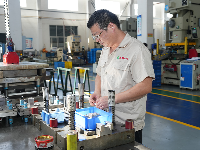
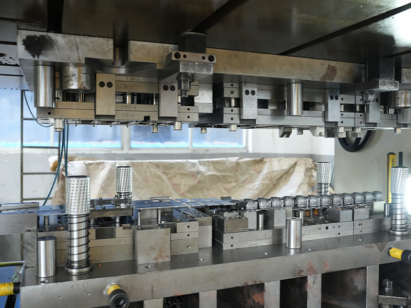
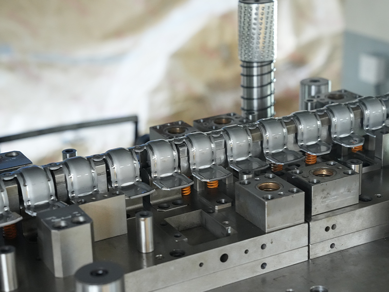
Home / News / Industry News / High-Precision Stamped Iron Solenoid Valve Housing Manufacturing Processes

The stamped stainless steel electronic plug-in is a precision-engineered component manufactured using advanced stamping techniques. Made from high-quality stainless steel, this part offers exceptional...
See Details
Our wear-resistant and high-pressure stainless steel shim is engineered to withstand conditions and provide exceptional performance in a variety of industrial applications. Made from premium-grade sta...
See Details
The Stamped Stainless Steel Heat Shield is a precision-formed automotive component designed to protect critical systems from excessive heat. Manufactured using advanced stamping technology, this heat ...
See Details
Our high pressure resistant stainless steel bracket is a robust, durable, and reliable solution for securing equipment in demanding environments where pressure and structural integrity are critical. M...
See Details
The Iron Engine Torque Converter Component Stamping Parts are precision-engineered components specifically designed for torque converters in automotive powertrain systems. Manufactured using high-stre...
See Details
Our iron friction plate is a high-quality, durable component designed for use in a variety of mechanical systems requiring efficient energy transfer and heat resistance. Manufactured using premium-gra...
See Details
Our corrosion-resistant automotive steel bracket is engineered for durability and performance in demanding automotive applications. Crafted from high-quality, corrosion-resistant steel, this bracket o...
See Details
Our automotive steel flange is engineered for precision, durability, and exceptional performance in various automotive applications. Made from high-quality carbon steel, stainless steel, or alloy stee...
See Details
The Stamped Aluminum Fan Heat Plate for New Energy Charging Pile Plug is a key component manufactured from aluminum alloy using stamping technology, widely used in the plug section of new energy vehic...
See Details
Our copper thin-walled bearing cage is an essential component designed for use in precision bearings, offering durability and efficient performance in various industrial applications. Constructed from...
See Details
Phosphor bronze connectors are precision-engineered electrical components made from a copper alloy that combines copper, tin, and phosphorus. This specialized material offers a unique blend of electri...
See Details
This CPU heat sink is engineered with high-purity copper as its core thermal conduction base, featuring a precision CNC-machined and mirror-polished contact surface that ensures gap-free contact with ...
See Detailscontact details
Address: No.6 Qiasheng North Road,Caoqiao Industrial Park,Xueyan Town,Wujin District,Changzhou City,Jiangsu Province
TEL: 86-15050692548
If You Are Interested In Our Products, Please Consult Us